Remarkably, much of modern design still depends on ideas that are more than two thousand years old. Architects, engineers, surveyors, and software developers all use the same geometric truths that classical geometers explored with a compass and straightedge. The tools may now include laser levels, CAD programs, folded paper, and reflective mirrors, but the underlying question is unchanged: how can you create a figure exactly, not approximately?
In geometry, a construction is a precise method for creating a figure using allowed tools and logical steps. A drawing is not enough by itself; what matters is that every point, segment, and angle is created from properties that can be justified. If you construct a midpoint, for example, you are not "eyeballing" the center. You are using geometry to guarantee that the two resulting parts are equal.
Traditional constructions use an unmarked straightedge and a compass. The straightedge draws lines through chosen points, and the compass copies distances or creates arcs and circles. Other tools can produce the same results in different ways. A folded sheet of paper can create a perpendicular or an angle bisector. A string can mark equal distances. A reflective device can help explore angle relationships. Dynamic geometry software can perform exact steps digitally while letting you drag points to test whether the relationships remain true.
Construction means creating a geometric object by a sequence of exact steps using allowed tools. Congruent figures have the same size and shape. A bisector divides a segment or angle into two equal parts. A perpendicular bisector is a line that passes through the midpoint of a segment and forms a right angle with it.
Formal constructions rely on a few powerful ideas: points on the same circle are all the same distance from the center, points on a perpendicular bisector are equidistant from the endpoints of a segment, and copied arcs can transfer angle information. These ideas let you build exact relationships from very simple moves.
Although compass-and-straightedge methods are the standard model, it is useful to compare several approaches. Different tools reveal the same geometric truths in different forms.
Compass and straightedge methods are the classical approach. The compass preserves a distance such as \(\overline{AB}\), and the straightedge connects points with lines. This method emphasizes logic and proof because each step depends on a known property.
Paper folding can produce exact constructions too. If you fold a segment so that one endpoint lands on the other, the crease is the perpendicular bisector. If you fold one side of an angle onto the other, the crease is the angle bisector. These results work because every point on the crease is equally distant from matched points after the fold.
Dynamic geometry software such as GeoGebra lets you carry out exact digital constructions. Its advantage is that you can drag points and watch the construction hold its properties. If a constructed line remains perpendicular while the figure moves, that is strong evidence that the steps were truly geometric, not just visual.
String and reflective devices are less common in formal classroom work, but they are useful for understanding. A taut string can transfer a distance in much the same way as a compass radius. Reflective tools can help investigate angle relationships, especially when exploring symmetry. The key idea is that the method must preserve the intended geometric relationship.
You already know that congruent segments have equal length, congruent angles have equal measure, perpendicular lines meet at an angle of \(90^\circ\), and parallel lines never intersect in a plane. Constructions give exact ways to create those relationships instead of estimating them.
Whenever you perform a construction, work lightly with pencil marks at first. Construction arcs are part of the reasoning, so they should remain visible until the final figure is complete. In geometric work, those arcs are not messy extra marks; they are evidence.
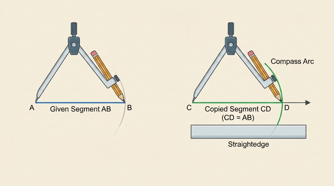
To copy a segment means to construct a new segment congruent to a given one. Suppose the given segment is \(\overline{AB}\), and you want a new segment starting at point \(C\). The distance transfer shown in [Figure 1] works because a compass can preserve the exact length \(AB\) while moving to a new location.
Procedure: Draw a ray starting at \(C\). Open the compass so its width is exactly the length of \(\overline{AB}\). Without changing the compass width, place the compass point at \(C\) and draw an arc that intersects the ray at point \(D\). Then \(\overline{CD}\cong\overline{AB}\).
The logic is simple but powerful. The compass opening equals \(AB\), and point \(D\) lies on the arc centered at \(C\) with that radius. Therefore \(CD = AB\). This is an exact copy, not an estimate from a ruler.
This construction is foundational because many other constructions depend on transferring equal lengths. For instance, constructing an equilateral triangle starts by copying the same segment length as a radius from two endpoints.
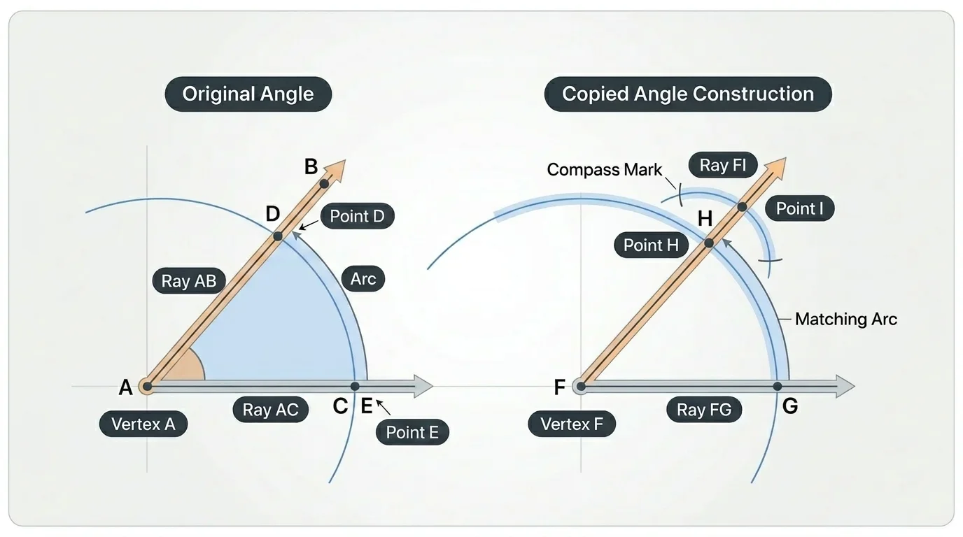
To copy an angle, you do more than match its appearance. You reproduce the exact opening by matching both an arc and the distance between the arc's intersection points, as shown in [Figure 2]. Suppose the original angle is \(\angle ABC\), and you want a congruent angle with vertex \(D\).
Procedure: Draw a ray starting at \(D\). With compass center at \(B\), draw an arc that intersects the sides of the original angle at points \(E\) and \(F\). Using the same compass width, draw a matching arc centered at \(D\), intersecting the new ray at \(G\). Then set the compass to the distance \(EF\). With center \(G\), draw an arc that intersects the new arc at point \(H\). Draw ray \(DH\). The resulting angle \(\angle GDH\) is congruent to \(\angle EBF\), so the new angle matches the original.
Why does this work? The equal arcs guarantee the same radius from each vertex, and the copied chord length \(EF\) fixes the opening between the rays. In effect, you are recreating the same circular slice at a new location.
Later, this same method becomes a key tool for constructing parallel lines because corresponding or alternate interior angles can be made equal by copying an angle to a new point.
To bisect a segment means to find its midpoint, the point that divides it into two congruent segments. The intersecting-arc method in [Figure 3] works because intersection points of equal-radius arcs are equidistant from the segment's endpoints.
Suppose you are given \(\overline{AB}\). Open the compass to a radius greater than half of \(AB\). Draw an arc centered at \(A\) above and below the segment. Using the same radius, draw arcs centered at \(B\) so that they intersect the first pair at points \(P\) and \(Q\). Draw line \(PQ\). This line crosses \(\overline{AB}\) at its midpoint \(M\).
Why is \(M\) the midpoint? Because every point on line \(PQ\) is equidistant from \(A\) and \(B\). In particular, the point where \(PQ\) meets \(\overline{AB}\) must be the unique point on the segment with \(AM = MB\).
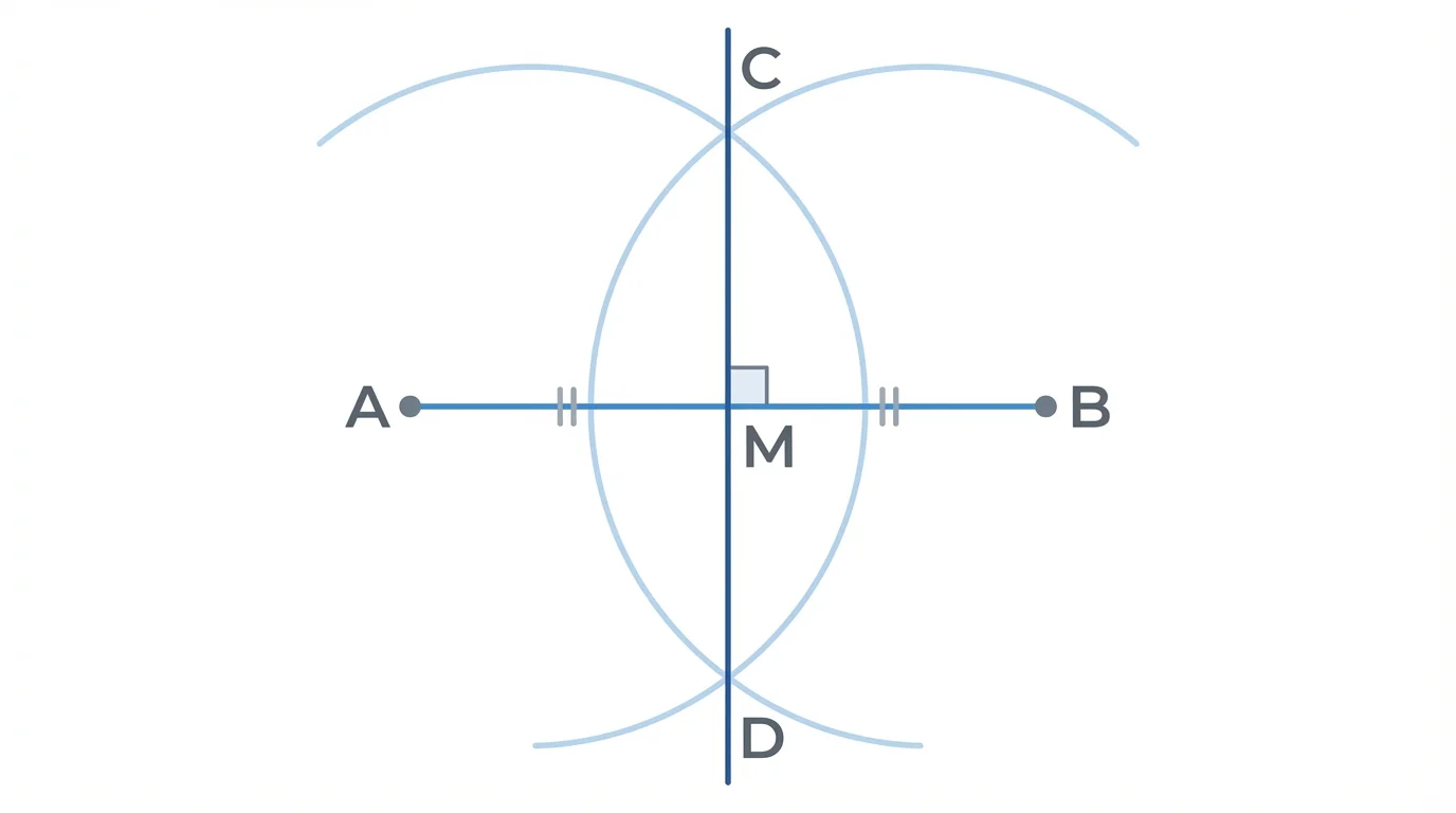
Notice that this construction gives more than just the midpoint. The line through \(P\) and \(Q\) is also perpendicular to \(\overline{AB}\). So one set of compass arcs produces two important results at once.
Why equal-radius arcs are so useful
Whenever you draw arcs of the same radius from two different points, the intersection points are forced to be the same distance from both centers. That equidistance is exactly the condition needed for midpoint and perpendicular bisector constructions. Much of geometric construction is really about creating and exploiting equal distances.
Paper folding gives a beautiful physical version of the same idea. If you fold \(A\) onto \(B\), the crease contains all points equally distant from \(A\) and \(B\), so the crease is the perpendicular bisector. The fold acts like a geometric proof you can hold in your hand.
An angle bisector is a ray that divides an angle into two congruent angles. Given \(\angle ABC\), place the compass at \(B\) and draw an arc intersecting the sides of the angle at \(E\) and \(F\). Then, using the same radius, draw arcs centered at \(E\) and \(F\) so that they intersect at point \(P\) inside the angle. Draw ray \(BP\).
The result is that \(m\angle EBP = m\angle PBF\). The reason is that \(BE = BF\) because both are radii of the first arc, \(EP = FP\) because both are radii of the second set of arcs, and \(BP\) is common. This creates two congruent triangles, which force the angle measures to be equal.
This is one of the clearest examples of construction and proof working together. You are not just making a line that looks central. You are building a pair of congruent triangles that guarantee the angle has been split equally.
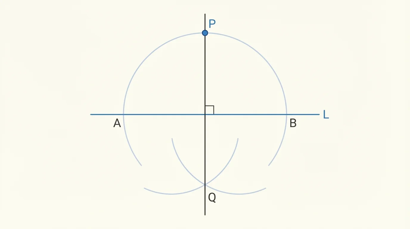
A perpendicular line forms a right angle with another line. There are two common cases, and the off-line case is illustrated in [Figure 4]: constructing a perpendicular through a point on the line and constructing one through a point not on the line.
Through a point on the line: Suppose point \(P\) lies on line \(\ell\). Mark two points \(A\) and \(B\) on \(\ell\) so that \(AP = PB\). Then use arcs from \(A\) and \(B\) with equal radius to intersect above the line at \(Q\). Draw line \(PQ\). Because \(P\) is the midpoint of \(\overline{AB}\), line \(PQ\) is the perpendicular bisector of \(\overline{AB}\), so it is perpendicular to \(\ell\).
Through a point not on the line: Suppose point \(P\) is not on line \(\ell\). Draw an arc centered at \(P\) that intersects \(\ell\) at points \(A\) and \(B\). Then construct the perpendicular bisector of \(\overline{AB}\). Since \(P\) is equidistant from \(A\) and \(B\), it lies on that perpendicular bisector, so the constructed line passes through \(P\) and is perpendicular to \(\ell\).
In both cases, the hidden engine is the same: equidistant points determine a perpendicular bisector. This idea connects naturally to the earlier midpoint construction.
The perpendicular bisector of a segment combines two ideas at once. It passes through the midpoint of the segment, and it is perpendicular to the segment. For \(\overline{AB}\), the standard construction is exactly the arc method used when bisecting a segment: equal-radius arcs from \(A\) and \(B\) intersect above and below the segment, and the line through those intersections is the perpendicular bisector.
This line has an important property: every point on it is equidistant from \(A\) and \(B\). Conversely, any point equidistant from \(A\) and \(B\) must lie on the perpendicular bisector. That makes it useful in proofs and in real applications such as locating a point that is equally far from two objects.
As seen earlier with the intersecting arcs in [Figure 3], one construction can produce a midpoint and a right angle simultaneously. Geometry often rewards methods that create several facts at once.
A parallel line through a point not on a given line can be built by copying an angle, and the corresponding-angle strategy appears in [Figure 5]. Suppose line \(\ell\) is given, and point \(P\) is not on \(\ell\).
One common method is this: draw a transversal from a point \(A\) on \(\ell\) to \(P\). Now copy the angle formed by the transversal and \(\ell\) at point \(P\), using one ray along \(\overline{PA}\). The new ray through \(P\) creates an angle congruent to the original corresponding angle, so the resulting line through \(P\) is parallel to \(\ell\).
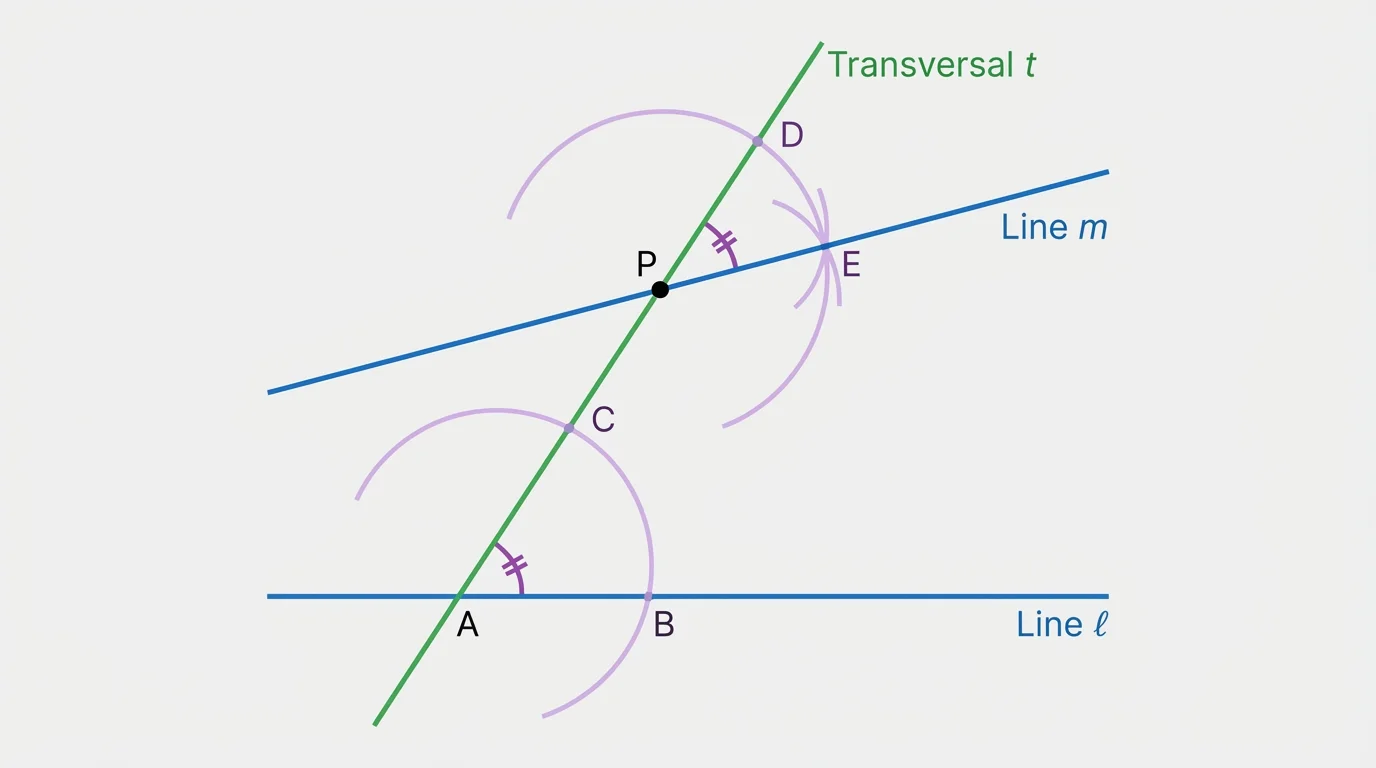
Why does this work? If a pair of corresponding angles are congruent, then the lines cut by the transversal are parallel. So this construction turns angle copying into line construction. In practical drafting, this is one of the most important exact methods because parallel edges appear everywhere.
A paper-folding version is also possible. If you fold the paper so that a line through \(P\) aligns with the given line's direction, the crease can represent a parallel relationship. Dynamic software makes this especially clear because dragging the original line preserves the copied-angle condition and the lines remain parallel.
Knowing the steps is important, but understanding why the steps work is what turns a procedure into geometry.
Worked example 1: Copy a segment of length \(\overline{AB}\) starting from point \(C\)
You are given segment \(\overline{AB}\) and a point \(C\) with a ray beginning at \(C\). Construct \(\overline{CD}\) so that \(\overline{CD} \cong \overline{AB}\).
Step 1: Draw the destination path.
Use the straightedge to draw a ray starting at \(C\).
Step 2: Capture the given distance.
Open the compass so the point and pencil rest on \(A\) and \(B\). The compass width is now \(AB\).
Step 3: Transfer the distance.
Without changing the compass width, place the compass point at \(C\) and draw an arc that crosses the ray at \(D\).
Step 4: State the result.
Because \(D\) lies on a circle centered at \(C\) with radius \(AB\), it follows that \(CD = AB\).
Therefore, \(\overline{CD} \cong \overline{AB}\).
This same distance-transfer idea appears again when constructing equal sides, locating points on circles, and setting up later proofs involving congruent triangles.
Worked example 2: Explain why an angle bisector construction is correct
Given \(\angle ABC\), arcs from \(B\) meet the sides at \(E\) and \(F\). Equal-radius arcs from \(E\) and \(F\) meet at \(P\). Show that \(BP\) bisects the angle.
Step 1: Identify equal lengths from compass moves.
Because \(E\) and \(F\) lie on the same arc centered at \(B\), \(BE = BF\).
Step 2: Use the second pair of arcs.
Because \(P\) lies on equal-radius arcs centered at \(E\) and \(F\), \(EP = FP\).
Step 3: Add the shared side.
Segment \(BP\) is common to both triangles, so \(BP = BP\).
Step 4: Conclude triangle congruence.
Triangles \(\triangle BEP\) and \(\triangle BFP\) are congruent by \(SSS\).
Step 5: Translate congruence into angle equality.
Corresponding angles are equal, so \(\angle EBP = \angle PBF\).
Thus, \(BP\) is the angle bisector of \(\angle ABC\).
Notice how the proof depends entirely on equal distances created by the compass. Construction marks and proof statements fit together perfectly.
Worked example 3: Construct a line through \(P\) parallel to line \(\ell\)
You are given line \(\ell\) and a point \(P\) not on it.
Step 1: Draw a transversal.
Choose a point \(A\) on \(\ell\) and draw \(\overline{AP}\).
Step 2: Identify the angle to copy.
Use the angle formed by \(\ell\) and \(\overline{AP}\) at \(A\).
Step 3: Copy that angle at \(P\).
Use the standard angle-copy construction so that one side of the new angle lies along \(\overline{PA}\).
Step 4: Draw the new line.
The second ray of the copied angle defines line \(m\) through \(P\).
Step 5: Justify parallelism.
The copied angle and the original angle are corresponding angles made by transversal \(AP\). Since corresponding angles are congruent, \(m \parallel \ell\).
Final result: \(m \parallel \ell\).
This is really an angle argument disguised as a line construction. Parallel lines are often built by controlling angle relationships rather than distance alone.
Formal constructions are not just school exercises. In engineering drawing, copying lengths and angles is essential when producing machine parts that must fit together exactly. A misplaced bisector can change a component's symmetry, and a nearly parallel edge can create serious tolerance problems.
Surveyors use perpendicular and parallel relationships when laying out property boundaries, road alignments, and building corners. If a foundation corner is not truly perpendicular, the error spreads across the entire structure. Exact geometric methods help prevent that.
In digital design, software automates many of these steps, but the geometry is the same. A CAD system that constructs a perpendicular bisector is still relying on equidistant points, just as the hand-drawn method does. The advantage of software is speed and adaptability, not different mathematics.
Some origami axioms can solve construction problems that are impossible with compass and straightedge alone. Paper folding is not just a craft technique; it is a powerful geometric system with its own formal rules.
Even in art and product design, these constructions matter. Logos, furniture layouts, stage sets, and camera framing often depend on symmetry, equal spacing, and precise directional relationships. Geometry is what keeps the design intentional instead of accidental.
One common mistake is changing the compass width by accident. In a copying construction, even a tiny change breaks the congruence. Another error is using a radius that is too small when constructing intersecting arcs for a midpoint or perpendicular bisector; if the arcs do not intersect, the construction cannot proceed.
Students also sometimes erase the arcs too soon. But those arcs record the reason the figure is correct. In a formal construction, visible arc intersections matter just as much as the final line or point.
Another subtle error is confusing a line that looks centered with a true bisector. The purpose of construction is to replace visual guessing with guaranteed relationships such as \(AM = MB\), \(\angle 1 = \angle 2\), \(\ell_1 \perp \ell_2\), or \(\ell_1 \parallel \ell_2\).
Finally, whenever possible, connect the finished figure to a theorem or definition. If you copied a segment, state that the compass preserved distance. If you made a perpendicular bisector, state that the arc intersections are equidistant from the endpoints. Geometry becomes much clearer when every step has a reason.